Micro Electro-Mechanical Systems (MEMS) - Accelerometers
Goal(s)
Main objective
MEMS sensors include a variety of transducers based on special micromachining of silicon. This allows to create sensor families having tunable features, according to the specific needs.
One application of MEMS sensors are accelerometers, that measure linear acceleration and allow the analysis of vibrations and structures dynamic behaviour.
Description
Types
There are several types of MEMS accelerometers, all provided as an Integrated Circuit with some conditioning electronics on a board. MEMS accelerometers differ in the following parameters values:
- Methodology of measure: in function of the embedded circuit and the methodology of measure MEMS accelerometers can be capacitive and thermal.
- Full Scale (FS): range of acceleration values that can be measured
- Bandwidth (BW): frequency range in which the MEMS sensor operates.
- Resolution: minimum detectable change in acceleration, expressed in [mg]
- Noise Density: parameter related to resolution and expressed in [mg/√Hz]; through noise density integration over the noise bandwidth, sensor resolution is obtained.
- Sensitivity: also known as gain, is the output change per unit of input acceleration.
- Connection types: the accelerometers can be linked to the acquisition system using wired or wireless connections.
MEMS accelerometer can both work along linear degrees of freedom or along rotation degrees of freedom.
Functioning mode of capacitive MEMS
MEMS accelerometers can measure acceleration along a single axis or three normal axes to give the acceleration vector. Their working principle is the same of all accelerometers, made of a single degree of freedom oscillating system, along each of the measurement axes. An external frame is rigidly connected to the body whose acceleration has to be known and the internal mass is suspended on springs. A relative displacement sensor detects the relative motion between the external frame (the accelerometer case) and the internal mass: this motion depends upon the inertia force acting on the mass, which, in turn, is related to the sensor absolute acceleration. The relative motion between the frame and the mass is detected by means of a number of differential capacitors created on the same accelerometer structure: their combination results in a measurable output.
Dealing with MEMS sensing element, the whole structure is miniaturized and made of silicon: the external frame, the internal mass and the supporting beams acting as springs are all made of silicon: also the sensing elements are a series of differential capacitances in a comb shape, worked on the same silicon structure.
Functioning mode of thermal MEMS
Thermal convection based micro-electromechanical accelerometer is an acceleration sensor which is characterized by the lack of a solid proof mass. This feature confers to thermal mems a high shock survivability, a low cost fabrication and, at last, a convenient integration of the sensor with CMOS integrated circuit technology.
Thermal accelerometers sense acceleration by measuring the displacement of a fluid bubble present within a sealed cavity.
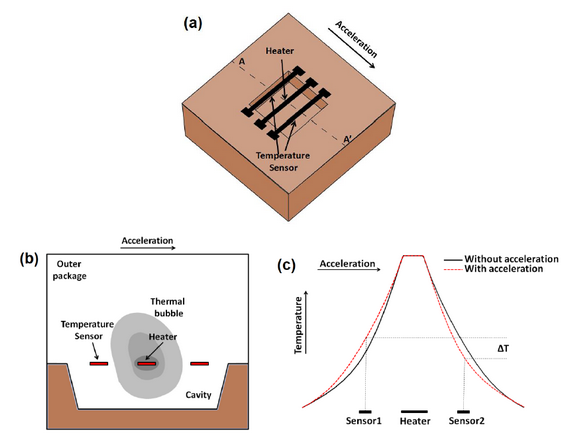
The operation of thermal inertial sensors is based on the natural convection of fluid. In figure 1(a) it is possible to observe a general structure of a single-axis thermal accelerometer, which consists of an electrical resistive heater, suspended at the centre of the cavity, and a pair of temperature sensors, which are placed symmetrically around the heater, while an outer cover encapsulates the fluid present in the cavity. The heat dissipation of the heater induces the formation of a hot thermal bubble of the fluid surrounding it. In steady, the temperature profile within the cavity remains symmetrical with respect to the heater, and the symmetrically placed temperature sensors detect identical temperatures. However, when an acceleration is applied, the temperature profile gets skewed due to physical displacement of the thermal bubble (figure 1(b)) and the temperature increases on one side of the heater and decreases at the other one
(figure 1(c)): the resultant differential temperature (ΔT) is proportional to the applied acceleration and is measured by the temperature sensors.
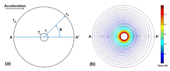
Simple geometries can be used for the accelerometer modelling: for instance, for the structure in figure 1(a), which has a centrally placed heater and working fluid enclosed by cavity and outer cover, the heater can be modelled as a cylindrical heat source and the outer cover as a larger cylinder at ambient temperature. Instead, a simplified model, as shown in figure 2(a), may consists of a spherical structure where the heater is a spherical source, and the outer cover is a larger sphere centring the heater and kept at ambient temperature.
.
Here:
- r and θ are the radial distance and angle of the spherical coordinate system respectively;
- The inner sphere represents the heater with radius <math>{r}_{i}</math>and surface temperature <math>{T}_{i}</math>;
- the outer sphere represents the cavity wall surface having radius <math>{r}_{0}</math>and wall temperature <math>{T}_{0}</math>(where <math>{T}_{i}> {T}_{0}</math>);
- AA' represents the vertical axis along midsection;
- <math>R={r}_{0}/{r}_{i}</math>is the ratio of the outer to inner sphere radius.
The concentric cylinder model is generally used for single-axis accelerometers, while concentric sphere for the dual axis ones. In three-axis accelerometers, the x and y-axes accelerations are applied in-plane, while the z-axis acceleration is applied out-of-plane and these too can be modelled with concentric spheres.
The governing equations predicting temperature profile of a thermal accelerometer device are based on the principle of conservation of mass, momentum and energy, but since the structure of a practical accelerometer is quite complex, it cannot be easily analysed by means of the analytical equations. To study its various performance parameters like temperature profile, numerical simulators are required to be used, like ANSYS, CoventorWare, and COMSOL Multiphysics.
For further information on thermal accelerometers in MEMS process and in CMOS-MEMS process, see.
In conclusion, the advantages of thermal MEMS, include a superior shock survival, simplistic compact structure, low cost, wide measurement range, and integrability with CMOS integrated circuit technology.
In spite of the advantages, thermal inertial sensors in their present form have a sensitivity and frequency response that restricts the possible fields of application and, moreover, sensitivity and bandwidth improvement is still an active research area.
Process/event to be detected or monitored
According to their design and the related electronics, MEMS accelerometers can be used for low level accelerations typical of operational conditions, up to shocks. In most cases and applications their performances are fit for monitoring purposes: through a wide number of sensors properly placed on structures, their dynamic behaviour can be described (e.g. modal parameters, principal mode shapes, etc.). Besides, if a continuous monitoring system is adopted damages or geometry changes in time can be detected with respect to the initial state, i.e. when the monitoring system is installed. With a well-designed MEMS accelerometers network, part of a continuous SHM system, eventual anomalous vibrations, interesting few structural/non-structural elements or the whole structure, can be measured, helping in maintenance procedures.
Physical quantity to be measured (e.g. actions, displacements, deformations, dynamic structural properties, material properties including mechanical, electrical and chemical properties, relative displacements of the two sides of a crack, etc.).
The output, which can both be analog (voltage or current) or digital (usually in terms of number of least significant bits) is directly related to the quantity being measured, which is acceleration. In case this is linear the output can be expressed in m/s2, or multiples of gravity (in g). In case of rotational acceleration the measurement units are typically rad/s2.
Induced damage to the structure during the measurement
No damage induced.
General characteristics
Measurement type (static or dynamic, local or global, short-term or continuous, etc.)
The design of MEMS accelerometers makes them g-sensitive, this means that their lower bound can extend to 0 Hz, which means capability to measure static or quasi static quantities. Therefore, they are suitable to measure tilt, as the projection of gravity along the measurement axis.
Their natural use is for dynamic acceleration measurements: each sensor can cover a point measurement over a single axis or three axes. Sensors can be considered alone, providing the evolution in time about the dynamics of a single point, or many of them can be evaluated together to perform more advanced dynamic approaches like modal analysis.
MEMS accelerometers can be employed for both short-term and continuous testing; besides, they can be used to describe the behavior of both local structural elements and the global structure.
Measurement range
As accelerometers work below resonance, the MEMS accelerometer performances depend upon the natural frequency of the silicon structure, which can be designed to reach bandwidths from some hundreds of Hertz up to some thousands, for sure redundant for monitoring applications, mainly requiring low-frequency ranges and low full scales.
The full scale can also be adjusted thanks to specific electronic hardware: full scale for the MEMS commonly adopted in monitoring applications can range from fractions of gravity up to some g, even if it is not so uncommon to have full scales of several hundred g, for specific applications, not related to monitoring.
Measurement accuracy
MEMS accelerometers have a measurement accuracy changeable based on multiple variables: setted sensors parameters (sampling frequency, FS, resolution, sensitivity, etc.), signal to noise ratio, energy of the input excitation, fixing type of the board in the sensor case.
Indeed, MEMS accelerometers can provide an analog output, though these are not so common today, or an already digitized output; they require a power supply typically in the range 0-5 V and also the output is within the mentioned range; this bias requires careful attention in case the output signal undergoes integration or other mathematical calculations.
Other issues specific of SHM applications are related to the board, acting as a dynamic system between the vibrating body and the sensor itself: care must be devoted to ensure that the vibration to be measured is properly transmitted to the sensor without attenuation of amplification.
Often MEMS accelerometers already have on-board temperature sensors to help compensating temperature drifts.
The main feature making these sensors different from quartz accelerometers for similar applications, apart from the sensitivity to gravity, is the signal to noise ratio, which is still about one order of magnitude higher in case of common MEMS accelerometer: while with robust input all accelerometers are expected to show similar performances, in case of operational measurements, with a very low input excitation, the MEMS accelerometer response can be buried in the background noise: this also warns against the attempt to couple MEMS accelerometers to A/D converters with a high number of bits, to avoid any resource waste.
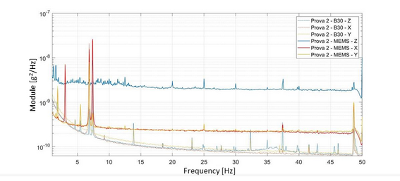
The noise floor is often declared in terms of power spectral density in a given frequency band. A comparison in terms of noise floor between a MEMS triaxial accelerometer (continuous lines) and a piezoelectric triaxial accelerometer (dashed lines) is given in the figure below, showing how main frequencies are well identifiable in both sensors types, even if an higher noise floor characterise the MEMS ones.
Background (evolution through the years)
In the second half of the 1950s, first papers regarding MEMS technology were published (C.S. Smith, 1954), describing piezoresistive effects in silicon and germanium. First MEMS applications are related to silicon pressure sensors, which commercialization started in the USA at the end of the 1960s. The technology development was very fast, thanks to improvements in silicon processing and in micromachining. Small, rugged and inexpensive devices with always increasing performance were produced, ranging in different categories: accelerometers, strain gauges, pressure sensors, microphones, gyroscopes, etc. Fields of application of the technology, as consequence, increased through the years: MEMS sensors are applied in the automotive, medical, aerospace, automation industry. Accelerometers technology is continuously evolving and for instance - advanced surface micromachining techniques developed allow to sense in one, two or three axes. Through the improved performance, their market is expanding and it is expected to grow rapidly in the future.
Performance
General points of attention and requirements
Design criteria and requirements for the design of the survey
Procedures for defining layout of the survey
Sensors layout should be carefully designed according to the phenomenon to be analysed and/or monitored. It would be advisable to have one sensor on each key node of the structure and on each relevant structural element. For example, if a modal analysis wants to be performed, sensors numbers and position must be properly chosen so that all structure principal mode shapes can be derived.
Another key point regards sensors parameters (full scale, sampling frequency, resolution, etc.), that should be adequately set according to the structure type, the desired measure and the frequency range of interest.
Moreover, if signals coming from different sensors should be combined in post-processing analysis, their synchronization must be guaranteed.
Sensibility of measurements to environmental conditions
MEMS accelerometers measurements can be influenced by environmental conditions, especially by temperature and during long-term/continuous testing. For this reason, it is advisable having an on-board temperature sensor, so that eventual temperature drift can be compensated.
Preparation
Procedures for calibration, initialisation, and post-installation verification
Standards for accelerometers calibration are illustrated in ISO 160063 (“Methods for the calibration of vibration and shock transducers”), including 8 parts regarding calibration procedures (i.e. Part 1, Part 11, Part 12, Part 13, Part 15, Part 21, Part 22, Part 41). For each method, the description of scopes and implementation steps is given, as well as specifications about apparatus requirements, variation ranges of measured quantities (frequency, acceleration amplitude, etc.), measurement uncertainties (divided into random and systemic) and recommendation for laboratory ambient conditions (temperature, humidity, etc.). Calibration procedure can provide several information about accelerometers characteristics, such as sensitivity, frequency response, resonant frequency, linearity, transverse sensitivity, etc.
Calibration methods can be divided in two different categories: absolute methods and relative methods. Absolute methods include tests in which sensors are subjected to a known input; some examples are:
- Gravity inversion test: each MEMS accelerometer axis is rotated of 180° along gravity direction, experimenting known acceleration of +1g and -1g.
- Drop test: accelerometer is dropped in gravity direction from different heights. The acceleration during the sensor free-fall is measured and compared with the expected g value, evaluating its sensitivity.
- Gravimetric test
- Calibration by laser interferometry
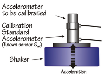
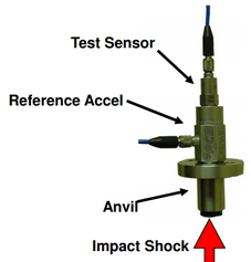
Relative methods, instead, calibrate the accelerometer to be tested by comparing its output with a reference sensor, previously calibrated, when they’re subjected to the same input acceleration. Characteristics of the reference sensor and of the exciter must be carefully chosen according to the test to be performed; in this regard, some recommendations are given in ISO 16063 Part 21 and Part 22, about vibration and shock calibration, respectively, by comparison to a reference transducer. Among relative calibration methods, the more commonly used are:
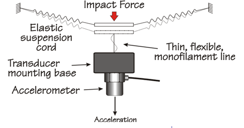
- Back-to-back method: reference and tested accelerometer are mounted “back-to-back” and subjected to the same acceleration imposed by an exciter. These methods are used both for vibration calibration and shock calibration. In the first case, a vibration exciter is set to different frequencies and acceleration levels; the reference accelerometer can be both internal and external to exciter. In case of shock calibration, instead, coupled sensors are subjected to shock pulse, measuring the ratio between peaks acceleration to get sensitivity and event duration.
- Handheld shaker: easy to perform and quick test. The shaker has an internal reference accelerometer and provides a fixed g force via a built-in servo-stabilization.
- Portable vibration calibrator
Procedures for estimating the component of measurement uncertainty resulting from calibration of the data acquisition system (calibration uncertainty)
Some recommendations are given in ISO 160063 (vibration calibration of rectilinear accelerometers (with or without amplifier) to obtain magnitude and phase of the complex sensitivity.
Requirements for data acquisition depending on the measured physical quantity (e.g. based on the variation rate)
Not applicable.
Performance
Requirements and recommendations for maintenance during operation (in case of continuous maintenance)
Not applicable.
Criteria for the successive surveying campaigns for updating the sensors. The campaigns include: (i) Georeferenced frame, i.e. the global location on the bridge; (ii) Alignment of sensor data, relative alignment of the data collected in a surveying; (iii) Multi-temporal registration to previous campaigns; and (iv) Diagnostics.
Not applicable.
Reporting
Lifespan of the technology and required maintenance (if applied for continuous monitoring)
Lifespan up to 5 years.
Interpretation and validation of results
Expected output (Format, e.g. numbers in a .txt file)
MEMS accelerometers output are accelerations, expressed in a measure of gravity (g) or in LSB (Least Significant Bit). Output length for each second of acquisition changes based on the setted sampling frequency.
Interpretation (e.g. each number of the file symbolizes the acceleration of a degree of freedom in the bridge)
MEMS accelerometers output consists in a measure of acceleration, along one or three axes. Based on sensors settings (e.g. sampling frequency) data quantity can be highly variable.
Validation
Not applicable.
Detection accuracy
Not applicable.
Advantages
MEMS accelerometer main advantages are:
- Low-cost technology.
- Applicable in a continuous SHM system.
- Easy transportation and installation
- Small size
- Depending on the application, sensors can be set with different parameters.
Disadvantages
- Not suitable when operational applications are characterized by low level inputs, due to their noise floor.
Possibility of automatising the measurements
A sensors network made by MEMS can be automatised by means of a gateway that manages sensors acquisition. In this way, sensors acquisition can depend on different rules: it can be continuous in time, limited to predefined intervals in a journey, etc.
Barriers
Existing standards
Applicability
Relevant knowledge fields
- Civil Engineering and Structural Health Monitoring
- Automotive Application
- Industrial Application
- Medical Application
Performance Indicators
- Frequency
- Vibrations/oscillations
- Prestressing cable failure
- Reinforcement bar failure/bending
- Tensioning force deficiency
- Loss of section
Type of structure
- Bridges
- Buildings
- Towers
- Transmission towers
- Windmills
Spatial scales addressed (whole structure vs specific asset elements)
Materials
Available knowledge
Reference projects
Bibliography
- ISO 16063-21(2003). Methods for the calibration of vibration and shock transducers-Part 21: Vibration calibration by comparison to a reference transducer.
- ISO 16063-22(2005). Methods for the calibration of vibration and shock transducers-Part 22: Shock calibration by comparison to a reference transducer.
- Angell, J.B., Terry, S.C., Barth, P.W. (1983), Silicon Micromechanical Devices, Scientific American, Vol. 248, pp. 44-55.
- Banks, D. Introduction to Microengineering, http://www.dbanks.demon.co.uk/ueng/what.html
- Brandt A. (2021). Noise and Vibratio Analysis: Signal Analysis and Experimental Procedures.
- Broch, J. T. (1972). Mechanical Vibration and Shock Measurement.
- Charles R. Farrar, K. W. (2012). Structural Health Monitoring: A Machine Learning Perspective.
- De Los Santos, H.J. (1999). Introduction to Microelectromechanical (MEM) Microwave Systems, Artech House Microwave Library, Artech House, Boston, MA.
- Ewins, D. J. (2000). Modal Testing: Theory, Practice and Application.
- Fraden, J. (2010). Handbook of Modern Sensors: Phisics, Designs, and Applications.
- Feynman, R. (1992). There’s Plenty of Room at the Bottom, Journal of Microelectromechanical Systems, Vol.1, No.1, pp. 60-66.
- Kempe, V. (2011). Inertial Mems: Principles and Practice.
- Kovacs, G.T.A. (1998). Micromachined Transducers Sourcebook, McGraw-Hill, New York, NY.
- Madou, M. (1997). Fundamentals of Microfabrication, CRC Press, Inc., Boca Raton, FL.
- Muller, R.S., Howe, R.T., Senturia, S.D., Smith, R.L., and White, R.M. [Eds.] (1991). Microsensors, IEEE Press, New York, NY.
- PRIME Faraday Partnership (2002). An Introduction to MEMS.
- Rahul Mukherjee, J. B. (2017). A review of Micromachined Thermal Accelerometers. Journal of Micromechanics and Microengineering.
- Richard S. Figliola, D. E. (2015). Theory and Design for Mechanical Measurements, 6th Edition.
- Soloman, S. (2010). Sensors Handbook.
- Steve P. Beeby, G. E. (2004). MEMS Mechanical Sensors (Microelectromechanical Systems Series).
- Thomas Beckwith, R. M. (2006). Mechanical Measurements 6th Edition.
- Trimmer, W.S. (1997). Micromechanics and MEMS: Classic and Seminal Papers to 1990, IEEE Press, New York, NY.
